Arduino > Encodeur de rotation
Contents (hide)
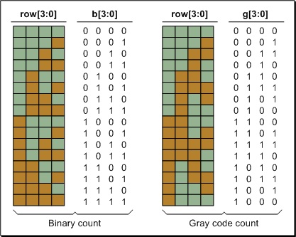
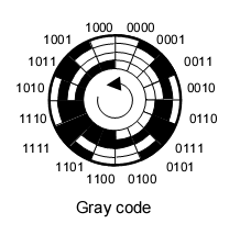
1. Le code Gray
2. Le code Gray relatif
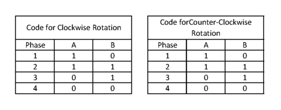
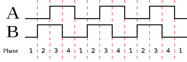
3. Encodeur incrémental générique (2 bit)
Les borne A et B de l'encodeur doivent être reliées aux interrupteurs de l'Arduino. Voir le tableau suivant pour déterminer les bonnes broches : http://arduino.cc/en/Reference/attachInterrupt  . Dans le cas de l'Arduino Leonardo, les broches des interrupteurs 0 et 1 sont 3 et 2.

Code (cliquer pour afficher/cacher)
#define encoder0PinA 2

#define encoder0PinB 3

volatile unsigned int encoder0Pos = 0;

void setup() {

        pinMode(encoder0PinA, INPUT);
        digitalWrite(encoder0PinA, HIGH); //Internal Pull-up
        pinMode(encoder0PinB, INPUT);
        digitalWrite(encoder0PinB, HIGH); //Internal Pull-up

        // encoder pin on interrupt 1 (pin 2)

        attachInterrupt(1, doEncoderA, CHANGE);

        // encoder pin on interrupt 0 (pin 3)

        attachInterrupt(0, doEncoderB, CHANGE);

        Serial.begin (57600);

}

void loop(){
        Serial.println( encoder0Pos );
        delay(50);
}

void doEncoderA(){

        // look for a low-to-high on channel A
        if (digitalRead(encoder0PinA) == HIGH) {

                // check channel B to see which way encoder is turning
                if (digitalRead(encoder0PinB) == LOW) {
                        encoder0Pos = encoder0Pos + 1;         // CW
                }
                else {
                        encoder0Pos = encoder0Pos - 1;         // CCW
                }
        }

        else   // must be a high-to-low edge on channel A
        {
                // check channel B to see which way encoder is turning
                if (digitalRead(encoder0PinB) == HIGH) {
                        encoder0Pos = encoder0Pos + 1;          // CW
                }
                else {
                        encoder0Pos = encoder0Pos - 1;          // CCW
                }
        }
        Serial.println (encoder0Pos, DEC);
        // use for debugging - remember to comment out

}

void doEncoderB(){

        // look for a low-to-high on channel B
        if (digitalRead(encoder0PinB) == HIGH) {

                // check channel A to see which way encoder is turning
                if (digitalRead(encoder0PinA) == HIGH) {
                        encoder0Pos = encoder0Pos + 1;         // CW
                }
                else {
                        encoder0Pos = encoder0Pos - 1;         // CCW
                }
        }

        // Look for a high-to-low on channel B

        else {
                // check channel B to see which way encoder is turning
                if (digitalRead(encoder0PinA) == LOW) {
                        encoder0Pos = encoder0Pos + 1;          // CW
                }
                else {
                        encoder0Pos = encoder0Pos - 1;          // CCW
                }
        }

}
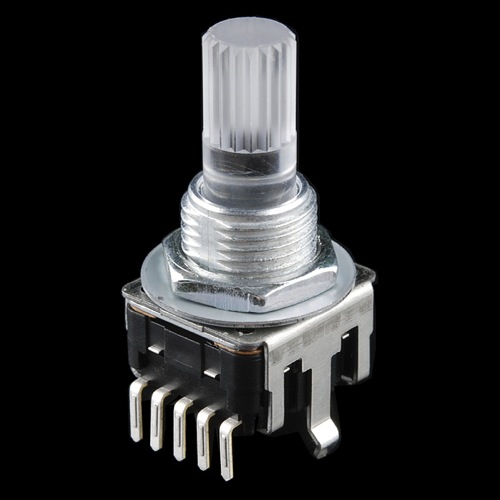
4. Encoder incrémental RGB avec interrupteur (2 bit, COM-10982)
- 24 pulsations par rotation
- COM-10982 chez Spikenzielabs

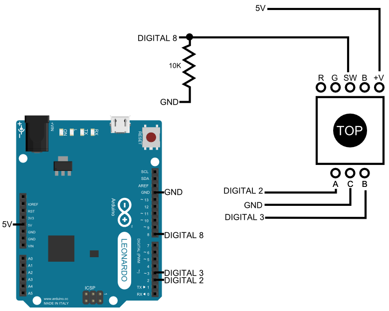
4.1 Juste les entrées
Code pour uniquement les entrées (cliquer pour afficher/cacher)
/*
How to use the inputs of Spikenzielabs Rotary Encoder - Illuminated (RGB) (COM-10982)
http://www.spikenzielabs.com/Catalog/index.php?main_page=product_info&cPath=8_105&products_id=825
Last modified by : Thomas Ouellet Fredericks
Last modification date : 2014/09/30
Based on this article : http://bildr.org/2012/08/rotary-encoder-arduino/
*/

// The following pins can not be changed as they are
// connected to the Leonardo interrupt pins :
// http://arduino.cc/en/Reference/attachInterrupt
#define ENCODER_A 2
#define ENCODER_B 3

#define ENCODER_SW 8

volatile boolean encoderMoved = false;
volatile byte encoderValue = 0;
volatile int relativeValue = 0;

int switchState;

void setup() {

        Serial.begin (57600);

        pinMode(ENCODER_A, INPUT_PULLUP); // turn interal pullup resistor on.
        pinMode(ENCODER_B, INPUT_PULLUP); // turn interal pullup resistor on.

        // call updateEncoder() when any high/low changed seen
        // on interrupt 0 (pin 2), or interrupt 1 (pin 3) :
        attachInterrupt(0, updateEncoder, CHANGE);
        attachInterrupt(1, updateEncoder, CHANGE);

        pinMode(ENCODER_SW, INPUT);
        switchState = digitalRead(ENCODER_SW);
}

void loop(){

        int newSwitchState =  digitalRead(ENCODER_SW);
        if ( switchState != newSwitchState ) {
                switchState = newSwitchState;
                Serial.print("SW ");
                Serial.println(switchState);
        }


        if ( encoderMoved ) {
                encoderMoved = false;
                Serial.print("Encoded ");
                Serial.println(encoderValue,BIN);

                Serial.print("Relative ");
                Serial.println(relativeValue);
        }

}


void updateEncoder(){

        encoderMoved = true;

        byte MSB = digitalRead(ENCODER_A); //MSB = most significant bit
        byte LSB = digitalRead(ENCODER_B); //LSB = least significant bit

        byte newEncodedValue = (MSB << 1) | LSB; //converting the 2 pin value to single number
        byte old_vs_new  = (encoderValue << 2) | newEncodedValue; //adding it to the previous encoded value

        if( old_vs_new == B1101 ||  old_vs_new == B0100 ||  old_vs_new == B0010 ||  old_vs_new == B1011) relativeValue ++;
        if( old_vs_new == B1110 ||  old_vs_new == B0111 ||  old_vs_new == B0001 ||  old_vs_new == B1000) relativeValue --;

        encoderValue = newEncodedValue; //store this value for next time
}
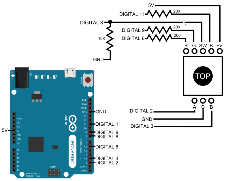
4.2 Entrées et sorties
Code pour les entrées et sorties (cliquer pour afficher/cacher)
#define ENCODER_A 2
#define ENCODER_B 3

#define LED_RED 6
#define LED_GREEN 9
#define LED_BLUE 11

#define ENCODER_SW 8

volatile boolean encoderMoved = false;
volatile byte encoderValue = 0;
volatile int relativeValue = 0;

byte r;
byte g;
byte b;

byte h;
byte s;
byte v;

int switchState;


void setup() {
        Serial.begin (57600);

        pinMode(ENCODER_A, INPUT);
        pinMode(ENCODER_B, INPUT);

        digitalWrite(ENCODER_A, HIGH); //turn pullup resistor on
        digitalWrite(ENCODER_B, HIGH); //turn pullup resistor on

        //call updateEncoder() when any high/low changed seen
        //on interrupt 0 (pin 2), or interrupt 1 (pin 3)
        attachInterrupt(0, updateEncoder, CHANGE);
        attachInterrupt(1, updateEncoder, CHANGE);

        pinMode(ENCODER_SW, INPUT);
        switchState = digitalRead(ENCODER_SW);

        h = 255;
        s = 255;
        v = 255;

}

void loop(){


        int newSwitchState =  digitalRead(ENCODER_SW);
        if ( switchState != newSwitchState ) {
                switchState = newSwitchState;
                Serial.print("SW: ");
                Serial.println(switchState);
        }


        if ( encoderMoved ) {
                encoderMoved = false;
                Serial.print("Encoded: ");
                Serial.print(encoderValue,BIN);
                Serial.print(" Relative: ");
                Serial.println(relativeValue);


                h = relativeValue % 256;

                HSV2RGB();

                Serial.print("Hue: ");
                Serial.print(h);
                Serial.print(" R: ");
                Serial.print(r);
                Serial.print(" G: ");
                Serial.print(g);
                Serial.print(" B: ");
                Serial.println(b);

                analogWrite(LED_RED,255-r);
                analogWrite(LED_GREEN,255-g);
                analogWrite(LED_BLUE,255-b);

        }

}


void updateEncoder(){

        encoderMoved = true;

        byte MSB = digitalRead(ENCODER_A); //MSB = most significant bit
        byte LSB = digitalRead(ENCODER_B); //LSB = least significant bit

        byte newEncodedValue = (MSB << 1) | LSB; //converting the 2 pin value to single number
        byte old_vs_new  = (encoderValue << 2) | newEncodedValue; //adding it to the previous encoded value

        if( old_vs_new == B1101 ||  old_vs_new == B0100 ||  old_vs_new == B0010 ||  old_vs_new == B1011) relativeValue ++;
        if( old_vs_new == B1110 ||  old_vs_new == B0111 ||  old_vs_new == B0001 ||  old_vs_new == B1000) relativeValue --;

        encoderValue = newEncodedValue; //store this value for next time
}


/* HSV to RGB conversion function with only integer
* math : values are between 0 and 255 */
void HSV2RGB() {
        byte region;
        unsigned int fpart,p, q, t;

        if(s == 0) {
                /* color is grayscale */
                r = g = b = v;
                return;
        }

        /* make hue 0-5 */
        region = h / 43;   // 4
        /* find remainder part, make it from 0-255 */
        fpart = (h - (region * 43)) * 6; // 120

        /* calculate temp vars, doing integer multiplication */
        p = (v * (255 - s)) >> 8; // 0
        q = (v * (255 - ((s * fpart) >> 8))) >> 8; // 255 * 120
        t = (v * (255 - ((s * (255 - fpart)) >> 8))) >> 8;

        /* assign temp vars based on color cone region */
        switch(region) {
                case 0:
                r = v; g = t; b = p; break;
                case 1:
                r = q; g = v; b = p; break;
                case 2:
                r = p; g = v; b = t; break;
                case 3:
                r = p; g = q; b = v; break;
                case 4:
                r = t; g = p; b = v; break;
                default:
                r = v; g = p; b = q; break;
        }


}
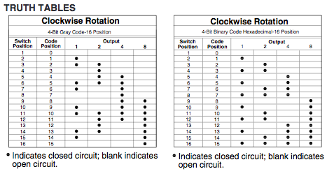
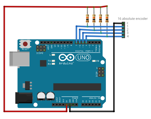
5. Encodeur absolu à 16 positions (4 bit): 25LB22-G
- http://www.digikey.ca/product-detail/en/25LB22-G/GH7299-ND/764241
- http://lgrws01.grayhill.com/web1/images/ProductImages/Series%2025L%20Encoder.pdf
Cet encodeur est composé de 4 interrupteurs. Effectuer la lecture numérique des 4 broches et consulter la table suivante pour déterminer la rotation.
Code (cliquer pour afficher/cacher)
/*

Thomas Ouellet Fredericks

*/

// Connect ENCODER_C to GND

#define ENCODER_1 7
#define ENCODER_2 6
#define ENCODER_4 5
#define ENCODER_8 4


void setup() {

        Serial.begin(57600);

        pinMode(ENCODER_1, INPUT);
        pinMode(ENCODER_2, INPUT);
        pinMode(ENCODER_4, INPUT);
        pinMode(ENCODER_8, INPUT);

        digitalWrite(ENCODER_1, HIGH);
        digitalWrite(ENCODER_2, HIGH);
        digitalWrite(ENCODER_4, HIGH);
        digitalWrite(ENCODER_8, HIGH);


}

void loop() {

        byte value = (digitalRead(ENCODER_8) << 3) | (digitalRead(ENCODER_4) << 2) | (digitalRead(ENCODER_2)) << 1 | digitalRead(ENCODER_1);

        Serial.print(value, BIN);
        Serial.print(' ');
        Serial.println(value);
        delay(100);


}