Arduino > ExempleDémultiplexeurPWMTLC5940
(ré-aiguillé depuis Arduino.TLC5940)
Contents (hide)
1. Introduction
Le TLC5940 est un circuit intégré qui permet de générer 16 canaux PWM. Il peut être branché en cascade pour fournir encore d'autres canaux PWM.
Chaque canal possède deux états: «sink» ou haute impédance. Aucun canal ne peut pas servir de «source».
Ce circuit intégré est particulièrement bien adapté au contrôle de DEL.
2. Logithèque
Un ou plusieurs TLC5940 peuvent être contrôlés avec la logithèque tlc5940arduino  . Elle peut être téléchargée ici: Tlc5940_rXXX.zip (les X correspondent au numéro de la version. Au moment d'écrire ce texte, la version était 014).
Pour l'installer, suivre les instructions pour l'installation d'une logithèque?. Il se peut que vous soyez obligés de la modifier si vous utilisez plusieurs TLC5940 (voir plus bas).
3. Description des broches
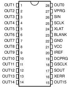
| XERR | open collector, wire or-ed output that lets you know a TLC5940 is over heated or has a burnt out LED. We can ignore this as it will always be on unless you have current using elements on all of the outputs. |
| SOUT | serial data out from the TLC5940. Unless you wish to try to read the error bits you do not need this to come to the Arduino. If you have more than one TLC5940 this is the line you daisy chain to the SIN of the next package. |
| DCPRG | this selects the source of the current limiter register, you could just tie it high. |
| XLAT | you will need this to latch data after shifting. |
| SCLK | you will need this to shift data. |
| SIN | serial in to TLC5940, this is the output from the Arduino. |
| VPRG | you need this to select either the current limit registers or the duty cycle registers for writing. |
| GSCLK | this is the clock for the PWM. We will reprogram TIMER2 in the Arduino to make this signal. That will cost us the native PWM on that timer, digital 11 on a mega8, 11 and 3 on a mega168. |
| BLANK | this marks the end of a PWM cycle in addition to blanking the output. We will reprogram TIMER1 to generate this signal. That will cost us the native PWMs on digital 9 and digital 10. (Tie a real, physical pull-up resistor on this line to keep things blanked while your Arduino boots. Depending on your hardware, it is possible that the TLC5940 would come up in a configuration that would dissipate too much power.) |
4. Formule magique du IREF (broche 20 du TLC5940)
Pour trouver la valeur de la résistance branchée à IREF (broche 20), vous devez appliquer la formule suivante:
| valeur de la résistance = 39.06 / intensité de votre DEL |
D'habitude l'intensité est de 20 mA pour les petites DEL 5mm et 30 mA pour les grosses DEL 10mm. Par exemple, pour une intensité de 20 mA, la résistance idéale est de 1953 Ohm, mais 2000 Ohm fera très bien l'affaire.
5. Branchement


5.1 Cascade
Pour pouvoir utiliser plusieurs TLC5940 branchés en cascade, vous devez modifier le fichier tlc_config.h de la logithèque. Changez la ligne #define NUM_TLCS 1 pour #define NUM_TLCS 2 (ou le nombre de TLC5940 que vous voulez utiliser).


5.2 DEL RGB
Pour utiliser une DEL RGB elle doit avoir l'anode en commun:


6. Exemples
6.1 Kinght Rider
/*
Basic Pin setup:
------------                                  ---u----
ARDUINO   13|-> SCLK (pin 25)           OUT1 |1     28| OUT channel 0
12|                           OUT2 |2     27|-> GND (VPRG)
11|-> SIN (pin 26)            OUT3 |3     26|-> SIN (pin 11)
10|-> BLANK (pin 23)          OUT4 |4     25|-> SCLK (pin 13)
9|-> XLAT (pin 24)             .  |5     24|-> XLAT (pin 9)
8|                             .  |6     23|-> BLANK (pin 10)
7|                             .  |7     22|-> GND
6|                             .  |8     21|-> VCC (+5V)
5|                             .  |9     20|-> 2K Resistor -> GND
4|                             .  |10    19|-> +5V (DCPRG)
3|-> GSCLK (pin 18)            .  |11    18|-> GSCLK (pin 3)
2|                             .  |12    17|-> SOUT
1|                             .  |13    16|-> XERR
0|                           OUT14|14    15| OUT channel 15
------------                                  --------

-  Put the longer leg (anode) of the LEDs in the +5V and the shorter leg
(cathode) in OUT(0-15).
-  +5V from Arduino -> TLC pin 21 and 19     (VCC and DCPRG)
-  GND from Arduino -> TLC pin 22 and 27     (GND and VPRG)
-  digital 3        -> TLC pin 18            (GSCLK)
-  digital 9        -> TLC pin 24            (XLAT)
-  digital 10       -> TLC pin 23            (BLANK)
-  digital 11       -> TLC pin 26            (SIN)
-  digital 13       -> TLC pin 25            (SCLK)
-  The 2K resistor between TLC pin 20 and GND will let ~20mA through each
LED.  To be precise, it's I = 39.06 / R (in ohms).  This doesn't depend
on the LED driving voltage.
- (Optional): put a pull-up resistor (~10k) between +5V and BLANK so that
all the LEDs will turn off when the Arduino is reset.

If you are daisy-chaining more than one TLC, connect the SOUT of the first
TLC to the SIN of the next.  All the other pins should just be connected
together:
BLANK on Arduino -> BLANK of TLC1 -> BLANK of TLC2 -> ...
XLAT on Arduino  -> XLAT of TLC1  -> XLAT of TLC2  -> ...
The one exception is that each TLC needs it's own resistor between pin 20
and GND.

This library uses the PWM output ability of digital pins 3, 9, 10, and 11.
Do not use analogWrite(...) on these pins.

This sketch does the Knight Rider strobe across a line of LEDs.

Alex Leone <acleone ~AT~ gmail.com>, 2009-02-03 */

#include "Tlc5940.h"

void setup()
{
        /* Call Tlc.init() to setup the tlc.
        You can optionally pass an initial PWM value (0 - 4095) for all channels.*/
        Tlc.init();
}

/* This loop will create a Knight Rider-like effect if you have LEDs plugged
into all the TLC outputs.  NUM_TLCS is defined in "tlc_config.h" in the
library folder.  After editing tlc_config.h for your setup, delete the
Tlc5940.o file to save the changes. */

void loop()
{
        int direction = 1;
        for (int channel = 0; channel < NUM_TLCS * 16; channel += direction) {

                /* Tlc.clear() sets all the grayscale values to zero, but does not send
                them to the TLCs.  To actually send the data, call Tlc.update() */
                Tlc.clear();

                /* Tlc.set(channel (0-15), value (0-4095)) sets the grayscale value for
                one channel (15 is OUT15 on the first TLC, if multiple TLCs are daisy-
                chained, then channel = 16 would be OUT0 of the second TLC, etc.).

                value goes from off (0) to always on (4095).

                Like Tlc.clear(), this function only sets up the data, Tlc.update()
                will send the data. */
                if (channel == 0) {
                        direction = 1;
                } else {
                        Tlc.set(channel - 1, 1000);
                }
                Tlc.set(channel, 4095);
                if (channel != NUM_TLCS * 16 - 1) {
                        Tlc.set(channel + 1, 1000);
                } else {
                        direction = -1;
                }

                /* Tlc.update() sends the data to the TLCs.  This is when the LEDs will
                actually change. */
                Tlc.update();

                delay(75);
        }

}
6.2 Msg
Code Arduino
#include <msg.h>
#include "Tlc5940.h"


void message() {

        byte length = msg.availableBytes();
        if ( length > 0 )  {
                Tlc.clear();
                for ( int i =0; i < length; i++ ) {
                        byte b = msg.readByte();
                        // The TLC5940 accepts values between 0 and 4095.
                        // We multiply the value of 'b' by 16 to scale to the TLC5940's range.
                        Tlc.set(i, b * 16);
                }
                Tlc.update();
        }
}

void setup()
{
        // Setup msg with a command handler and a custom name.
        msg.setup(message,"TLC5940");

        // The TLC5940 uses pins 3,9,10,11,13 so we detach these pins
        // from msg's control.
        msg.detach(13);
        msg.detach(11);
        msg.detach(10);
        msg.detach(9);
        msg.detach(3);

        // Call Tlc.init() to setup the TLC.
        Tlc.init();
}

void loop()
{
        msg.loop();
}

