Arduino > Contrôle bidirectionnel d'un moteur CC
Contents (hide)
1. SN754410 ou L293D
La plupart des moteurs DC peuvent tourner dans les deux sens en inversant la polarité des câbles. Les circuits intégrés de type H-Bridge permettent d'alterner le sens de courant et donc de contrôler le sens de rotation d'un moteur. Le SN754410 ou le L293D sont des H-Bridge quasiment identiques et très populaires.

- 1A et 2A permettent de contrôler la direction d'un moteur (branché à 1Y et 2Y).
- 1,2EN permet de contrôler la vitesse du moteur par PWM.
| 1,2EN | 1A | 2A | Résultat |
|---|---|---|---|
| HIGH | HIGH | LOW | Le moteur tourne dans un sens |
| HIGH | LOW | HIGH | Le moteur tourne dans l'autre sens |
| LOW | - | - | Le moteur ne tourne pas |
- = peu importe
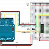
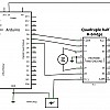
2. Circuit
2.1 Exemple de code qui contrôle le moteur avec Messenger
#include <Messenger.h>

// CREER UNE INSTANCE DE Messenger POUR RECEVOIR LES MESSAGES
Messenger messenger = Messenger();

/* LES  MESSAGES
*   "vitesseA α" :  α EST UN ENTIER ENTRE 0 ET 255 QUI DETERMINE LA VITESSE DU MOTEUR A
*   "directionA β" :  β EST UN ENTIER ENTRE 0 ET 1 QUI DETERMINE LA DIRECTION DU MOTEUR A
*/

int broche_vitesseA = 9; // LA BROCHE RELIEE AU CONTROLE DE LA VITESSE : 12EN
int broche_direction1A = 8; // LA BROCHE RELIEE AU PREMIER DE LA PAIRE POUR LA DIRECTION : 1A
int broche_direction2A = 7; // LA BROCHE RELIEE AU DEUXIEME DE LA PAIRE POUR LA DIRECTION : 2A

int vitesseA = 255; // LA VALEUR INITIALE QUI SERA APPLIQUEE A LA VITESSE DU MOTEUR
int directionA = 0; // LA VALEUR INITIALE QUI SERA APPLIQUEE A LA DIRECTION DU MOTEUR

void setup() {

        Serial.begin(57600);  // INITIALISER LA COMMUNICATION SERIE

        messenger.attach(messageReceived);   // LANCER messageReceived LORSQU'UN MESSAGE EST RECU

        // CONFIGURER LES BROCHES DU MOTEUR
        pinMode( broche_vitesseA , OUTPUT );
        pinMode( broche_direction1A , OUTPUT );
        pinMode( broche_direction2A , OUTPUT );

        // APPLIQUER LES VALEURS INITIALES
        analogWrite(broche_vitesseA,vitesseA);
        if ( directionA == 0 ) {
                digitalWrite( broche_direction1A , LOW );
                digitalWrite( broche_direction2A , HIGH );
        } else {
                digitalWrite( broche_direction1A , HIGH );
                digitalWrite( broche_direction2A , LOW );
        }

}

void loop() {

        while ( Serial.available( ) > 0 ) {
                messenger.process( Serial.read( ) ); // FOURNIR LES DONNEES SERIES RECUES A L'INSTANCE DE Messenger
        }
}

void messageReceived() {

        if ( messenger.checkString("vitesseA") ) {  // SI LE MESSAGE COMMENCE AVEC "vitesseA"...

                vitesseA = messenger.readInt(); // ...LIRE LA PROCHAINE DONNEE EN TANT QU'ENTIER (int)
                analogWrite(broche_vitesseA,vitesseA);    // APPLIQUER LA VALEUR AU MOTEUR

                Serial.println("Ok");

        } else  if ( messenger.checkString("directionA") ) {   // SI LE MESSAGE COMMENCE AVEC "directionA"...


                directionA = messenger.readInt(); // ...LIRE LA PROCHAINE DONNEE EN TANT QU'ENTIER (int)
                if ( directionA == 0 ) {  // APPLIQUER LA VALEUR AU MOTEUR
                        digitalWrite( broche_direction1A , LOW );
                        digitalWrite( broche_direction2A , HIGH );
                } else {
                        digitalWrite( broche_direction1A , HIGH );
                        digitalWrite( broche_direction2A , LOW );
                }
                Serial.println("Ok");

        } else {

                Serial.println("What?"); // IMPRIMER "What?" SI LE MESSAGE N'EST PAS RECONNU

        }

}
2.2 Exemple de code qui contrôle le moteur automatiquement
int broche_12EN = 9;
int broche_1A = 7;
int broche_2A = 8;


void setup() {
        pinMode(broche_12EN,OUTPUT);
        pinMode(broche_1A,OUTPUT);
        pinMode(broche_2A,OUTPUT);
}

void loop () {

        // Vitesse moyenne, direction 1 :
        analogWrite ( broche_12EN, 127 );
        digitalWrite( broche_1A  , HIGH);
        digitalWrite( broche_2A  , LOW);

        delay(1000);

        // Vitesse maximale, direction 2 :
        analogWrite ( broche_12EN, 255 );
        digitalWrite( broche_1A  , LOW);
        digitalWrite( broche_2A  , HIGH);

        delay(1000);

        // Vitesse maximale, direction 1 :
        digitalWrite ( broche_12EN, HIGH );
        digitalWrite( broche_1A  , HIGH);
        digitalWrite( broche_2A  , LOW);

        delay(1000);

        // Moteur off :
        digitalWrite ( broche_12EN, LOW );
        digitalWrite( broche_1A  , LOW);
        digitalWrite( broche_2A  , HIGH);

        delay(1000);

}
3. Circuit avancé
Ce circuit permet de libérer une sortie de l'Arduino à l'aide d'un transistor. Dans ce cas, on utilise un transistor PN2222 de type NPN (40V, 1A).
- PN2222 chez Digikey: http://www.digikey.ca/product-detail/en/PN2222ATF/PN2222ATFCT-ND/3504402
- Fiche technique: http://www.fairchildsemi.com/ds/PN/PN2222A.pdf


- E: «Emitter»
- B: «Base»
- C: «Collector»


3.1 Code Arduino
#define SPEEDPIN 11
#define DIRECTIONPIN 12

int spd;
int dir;

void setup() {

        pinMode(SPEEDPIN,OUTPUT);
        pinMode(DIRECTIONPIN,OUTPUT);

        dir = 1;
        spd = 125; // 0-255

}


void loop () {

        analogWrite(SPEEDPIN,spd);
        digitalWrite(DIRECTIONPIN,dir);

}


