Arduino > MOSFET
Une MOSFET est une Porte de transfert.
- Les IRL sont meilleures que les FQP
- Les IRL sont meilleures que IRF (10V gate)
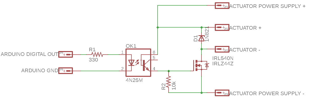
Not all MOSFETs are the same, and too many Arduino sites show the IRF series MOSFET. The IRF series require 10v (VGS = 10.0 V) at the gate to fully open at anywhere near rated loads, so we use the IRL series. Any logic level N-Channel MOSFET (VGS = 5.0 V) will work, and look for the lowest RDS(on) (Ω) resistance you can practically find, to limit heat buildup. Connect your DC load between + and the Drain (D) of the MOSFET. Connect the MOSFET Source (S) to ground, or negative terminal of your voltage source. We add two resistors, a 10k Ohm from the MOSFET Gate (G) to ground to ensure turnoff when Gate signal is removed, and a 125 Ohm resistor between the Arduino output and the MOSFET Gate (G). This protects the Arduino pin from too much current draw. The value is determined by the voltage of the Arduino pin (5v) divided by the max current we want to allow (40ma). The IRL540 shown has a built in snubber diode that prevents motor flyback from damaging the MOSFET or Arduino. The Arduino sends a HIGH signal to turn on the MOSFET, a LOW to turn it off, and can also use PWM (analogWrite on an appropriate pin) to control motor speed, lamp brightness, etc.
MOSFET isolée