Arduino > Exemple de moteur à pas bipolaire et SN754410 ou L293
Contents (hide)
1. LB82773
Le LB82773 est un moteur à pas unipolaire.

Identification des fils du moteur LB82773:
| Noir | ➡ | A+ |
| Jaune | ➡ | A- |
| Gris | ➡ | B+ |
| Rouge | ➡ | B- |
La logithèque Stepper execute la séquence suivante pour chaque step:
| Step | A+ | B+ | A- | B- |
| 1 | HIGH | HIGH | LOW | LOW |
| 2 | LOW | HIGH | HIGH | LOW |
| 3 | LOW | LOW | HIGH | HIGH |
| 4 | HIGH | LOW | LOW | HIGH |
2. Contrôle à quatre sorties
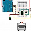
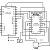
2.1 Circuit
2.2 Code
#include <Stepper.h>

#define STEPS_PER_REVOLUTION 48

// 1 2 3 4
// H H L L
// L H H L
// L L H H
// H L L H
// 1 & 3 are wired together
// 2 & 4 are wired together

#define HBRIDGE_EN 11
#define HBRIDGE_1 10
#define HBRIDGE_2 9
#define HBRIDGE_3 8
#define HBRIDGE_4 7

// The Stepper class takes the following arguments:
// Stepper( STEPS PER REVOLUTION, A+, B+, A-, B-);
Stepper myStepper( STEPS_PER_REVOLUTION, HBRIDGE_1, HBRIDGE_3,HBRIDGE_2,HBRIDGE_4 );

void setup() {

        // Turn motor on.
        pinMode(HBRIDGE_EN,OUTPUT);
        digitalWrite(HBRIDGE_EN,HIGH);

}

void loop() {
        // Step one step:
        myStepper.step(1);
        // Wait:
        delay(1000);
}
3. Contrôle à deux sorties
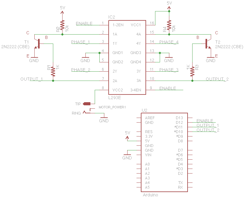
Avec des transistors, il est possible de concevoir un circuit qui va toujours invertir A+ et A-. De même avec B+ et B-. Il suffit donc uniquement de contrôler A+ et B+.
Dans le code et circuits suivants:
- OUTPUT_1 contrôle PHASE_1 (A+) et PHASE_2 (A-)
- OUTPUT_2 contrôle PHASE_3 (B+) et PHASE_4 (B-)
3.1 Circuit
3.2 Code
#include <Stepper.h>

#define STEPS_PER_REVOLUTION 48

#define ENABLE 12
#define OUTPUT_1 11
#define OUTPUT_2 10


Stepper myStepper(STEPS_PER_REVOLUTION, OUTPUT_1, OUTPUT_2);

void setup() {

        // Turn motor on.
        pinMode(ENABLE,OUTPUT);
        digitalWrite(ENABLE,HIGH);

}

void loop() {
        // Step one step:
        myStepper.step(1);
        // Wait:
        delay(500);
}


