Arduino > Rainbowduino
Contents (hide)
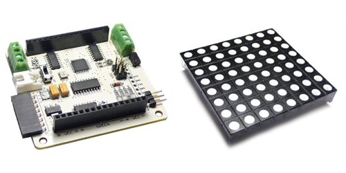
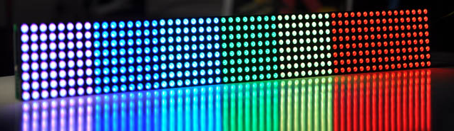
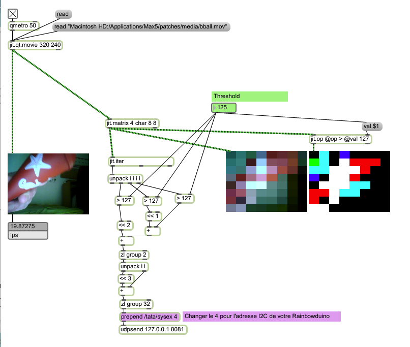
Permet de contrôler des matrices de DEL par I2C.


1. Télécharger le micrologiciel sur le Rainbowduino
1.1 Méthode avec un convertisseur USB vers série?
|
Broche du convertisseur USB vers série |
Broche du Rainbowduino |
|
DTR |
DTR |
|
RXD |
TXD |
|
TXD |
RXD |
|
5V |
VCC |
|
GND |
GND |
1.2 Méthode avec un Arduino lobotomisé?
|
Broche de l'Arduino lobotomisé |
Broche du Rainbowduino |
|
RESET |
DTR |
|
RXD |
RXD |
|
TXD |
TXD |
|
5V |
VCC |
|
GND |
GND |
2. Branchement I2C
|
Broche de l'Arduino maître |
Broche du Rainbowduino esclave |
|
Analog 4 |
SDA |
|
Analog 5 |
SCL |
|
5V |
VCC du terminal vert |
|
GND |
GND du terminal vert |
3. Exemple
3.1 Code Arduino maître
#include <Wire.h>


void setup() {

        Serial.begin(57600);
        Wire.begin(); // join i2c bus (address optional for master)

}

void loop() {

        while ( fourTenAvailable() ) {
                int channel = fourTenReadChannel();

                if ( channel == 13 ) {

                        Wire.beginTransmission( fourTenReadData() );

                }
                else if ( channel == 15) {

                        Wire.endTransmission();

                }
                else if (channel == 14) {

                        Wire.write( fourTenReadData() );

                }
        }

}


//fourTenStart

/*
______            _______
|  ____|          |__   __|
| |__ ___  _   _ _ __| | ___ _ __
|  __/ _ \| | | | '__| |/ _ \ '_ \
| | | (_) | |_| | |  | |  __/ | | |
|_|  \___/ \__,_|_|  |_|\___|_| |_|


Description
=============

FourTen est un protocole de communication tres simple et tres rapide.
Il permet d'envoyer des données dont la valeur se situe entre 0 et 1023 (10 bits)
sur 16 canaux numerotes de 0 a 15 (4 bits).


Installation
=============

Pour utiliser le protocole dans Arduino ou Wiring,
copier tout ce qui se trouve entre //fourTenStart et //fourTenEnd
et l'ajouter a la fin de votre sketch.


Utilisation
=============

# fourTenWrite(int canal, int donnee)
Permet d'envoyer un message fourTen.

# fourTenAvailable()
Retourne 1 si un message FourTen est disponible.
Retourne 0 sinon.

# int fourTenReadChannel()
Retourne le canal d'un message FourTen recu.

# int fourTenReadData()
Retourne la donnee d'un message FourTen recu.


Details du protocol FourTen
=============

Chaque message est construit a partir de deux octets:

octet 1           octet 2
bit 7 6 5 4 3 2 1 0 - 7 6 5 4 3 2 1 0
fonction 1 C C C C D D D   0 D D D D D D D

C: canal
D: donnee

octet 1:
bit    7 = 1
bits 6-3 = canal
bits 2-0 = bits 9-7 de la donnee
octet 2:
bit    7 = 0
bits 6-0 = bits 6-0 de la donnee

Le bit 7 de chaque octet sert a identifier si c'est
l'octet 1 ou 2. En excluant ces deux bits,
il reste donc 14 bits qui se subdivisent ainsi:
4 bits (canal) suivis de 10 bits (donnee)

Le canal peut avoir une valeur entre 0-15.
La donnee peut avoir une valeur entre 0-1023.

*/

void fourTenWrite(int channel, int data) {

        Serial.write( ( channel << 3 | ( ( data >> 7) & 0x07 )   )  | 0x80);
        Serial.write( data & 0x7F);

}


int fourTenBuffer;

int fourTenAvailable( ) {

        while ( Serial.available() ) {
                int data = Serial.read();

                if ( data & 0x80 ) {
                        fourTenBuffer = data & 0x7F;
                }
                else {
                        fourTenBuffer = ( fourTenBuffer << 7 ) | ( data & 0x7F );
                        return 1;
                }

        }

        return 0;
}


int fourTenReadChannel() {
        return fourTenBuffer>>10;
}

int fourTenReadData() {
        return fourTenBuffer & 0x3FF;
}

//fourTenEnd
3.2 Code Rainbowduino esclave
#include <Wire.h>

// Change the following line to change your Rainbowduino I2C address
#define I2C_ADDRESS 4


#ifndef Rainbow_h
#define Rainbow_h
//=============================================
//MBI5168
#define SH_DIR_OE    DDRC
#define SH_DIR_SDI   DDRC
#define SH_DIR_CLK   DDRC
#define SH_DIR_LE    DDRC

#define SH_BIT_OE    0x08
#define SH_BIT_SDI   0x01
#define SH_BIT_CLK   0x02
#define SH_BIT_LE    0x04

#define SH_PORT_OE   PORTC
#define SH_PORT_SDI  PORTC
#define SH_PORT_CLK  PORTC
#define SH_PORT_LE   PORTC
//============================================
#define clk_rising  {SH_PORT_CLK&=~SH_BIT_CLK;SH_PORT_CLK|=SH_BIT_CLK;}
#define le_high     {SH_PORT_LE|=SH_BIT_LE;}
#define le_low      {SH_PORT_LE&=~SH_BIT_LE;}
#define enable_oe   {SH_PORT_OE&=~SH_BIT_OE;}
#define disable_oe  {SH_PORT_OE|=SH_BIT_OE;}

#define shift_data_1     {SH_PORT_SDI|=SH_BIT_SDI;}
#define shift_data_0     {SH_PORT_SDI&=~SH_BIT_SDI;}
//============================================
#define open_line0	{PORTB=0x04;}
#define open_line1	{PORTB=0x02;}
#define open_line2	{PORTB=0x01;}
#define open_line3	{PORTD=0x80;}
#define open_line4	{PORTD=0x40;}
#define open_line5	{PORTD=0x20;}
#define open_line6	{PORTD=0x10;}
#define open_line7	{PORTD=0x08;}
#define close_all_line	{PORTD&=~0xf8;PORTB&=~0x07;}
//============================================

#define CheckRequest (g8Flag1&0x01)
#define SetRequest (g8Flag1|=0x01)
#define ClrRequest (g8Flag1&=~0x01)

//==============================================
#define waitingcmd 0x00
#define processing  0x01
#define checking  0x02

#define showPrefabnicatel 0x01
#define showChar 0x02
#define showColor 0x03
#endif

//=============================================================
unsigned char dots_color[2][3][8][4];  //define Two Buffs (one for Display ,the other for receive data)

//define the Gamma value for correct the different LED matrix
unsigned char GamaTab[16]=
{0xE7,0xE7,0xE7,0xE7,0xE7,0xE7,0xE7,0xE7,0xE7,0xE7,0xE7,0xE7,0xE7,0xE7,0xE7,0xE7};

//=============================================================
unsigned char line,level;
unsigned char Buffprt=0;
//unsigned char State=0;
unsigned char g8Flag1;
//unsigned char RainbowCMD[5]={0,0,0,0,0};

void setup()
{

        //Serial.begin(57600);
        //Serial.println("START");
        DDRD=0xff;
        DDRC=0xff;
        DDRB=0xff;
        PORTD=0;
        PORTB=0;
        Wire.begin(I2C_ADDRESS); // join i2c bus
        Wire.onReceive(receiveEvent); // define the receive function for receiving data from master
        //Wire.onRequest(requestEvent); // define the request function for the request from maseter
        init_timer2();  // initial the timer for scanning the LED matrix
}


void receiveEvent(int howMany)
{

        // unsigned char header = Wire.receive();
        //Serial.println(header,DEC);
        //if ( header == 32 ) {
        unsigned char i = 0;
        while(Wire.available()>0) {
                unsigned char d = Wire.receive();
                // Serial.println(d,DEC);
                unsigned char x = i / 4;
                unsigned char y = i % 4;
                // dots_color[2][3][8][4];
                // d = xxRGBRGB // xx(RGB n)(RGB n+1)
                dots_color[Buffprt][1][x][y] = ((d & B00100000) ? B11110000 : B00000000) | ((d & B00000100) ? B00001111 : B00000000);
                dots_color[Buffprt][0][x][y] = ((d & B00010000) ? B11110000 : B00000000) | ((d & B00000010) ? B00001111 : B00000000);
                dots_color[Buffprt][2][x][y] = ((d & B00001000) ? B11110000 : B00000000) | ((d & B00000001) ? B00001111 : B00000000);
                i++;
        }
        //Buffprt = (Buffprt + 1) % 2;
        //}


}

void loop() {

}


ISR(TIMER2_OVF_vect)          //Timer2  Service
{
        TCNT2 = GamaTab[level];    // Reset a  scanning time by gamma value table
        flash_next_line(line,level);  // sacan the next line in LED matrix level by level.
        line++;
        if(line>7)        // when have scaned all LEC the back to line 0 and add the level
        {
                line=0;
                level++;
                if(level>15)       level=0;
        }
}

void init_timer2(void)
{
        TCCR2A |= (1 << WGM21) | (1 << WGM20);
        TCCR2B |= (1<<CS22);   // by clk/64
        TCCR2B &= ~((1<<CS21) | (1<<CS20));   // by clk/64
        TCCR2B &= ~((1<<WGM21) | (1<<WGM20));   // Use normal mode
        ASSR |= (0<<AS2);       // Use internal clock - external clock not used in Arduino
        TIMSK2 |= (1<<TOIE2) | (0<<OCIE2B);   //Timer2 Overflow Interrupt Enable
        TCNT2 = GamaTab[0];
        sei();
}

//==============================================================
void shift_1_bit(unsigned char LS)  //shift 1 bit of  1 Byte color data into Shift register by clock
{
        if(LS)
        {
                shift_data_1;
        }
        else
        {
                shift_data_0;
        }
        clk_rising;
}
//==============================================================
void flash_next_line(unsigned char line,unsigned char level) // scan one line
{
        disable_oe;
        close_all_line;
        open_line(line);
        shift_24_bit(line,level);
        enable_oe;
}

//==============================================================
void shift_24_bit(unsigned char line,unsigned char level)   // display one line by the color level in buff
{
        unsigned char color=0,row=0;
        unsigned char data0=0,data1=0;
        le_high;
        for(color=0;color<3;color++)//GBR
        {
                for(row=0;row<4;row++)
                {
                        data1=dots_color[Buffprt][color][line][row]&0x0f;
                        data0=dots_color[Buffprt][color][line][row]>>4;

                        if(data0>level)   //gray scale,0x0f aways light
                        {
                                shift_1_bit(1);
                        }
                        else
                        {
                                shift_1_bit(0);
                        }

                        if(data1>level)
                        {
                                shift_1_bit(1);
                        }
                        else
                        {
                                shift_1_bit(0);
                        }
                }
        }
        le_low;
}


//==============================================================
void open_line(unsigned char line)     // open the scaning line
{
        switch(line)
        {
                case 0:
                {
                        open_line0;
                        break;
                }
                case 1:
                {
                        open_line1;
                        break;
                }
                case 2:
                {
                        open_line2;
                        break;
                }
                case 3:
                {
                        open_line3;
                        break;
                }
                case 4:
                {
                        open_line4;
                        break;
                }
                case 5:
                {
                        open_line5;
                        break;
                }
                case 6:
                {
                        open_line6;
                        break;
                }
                case 7:
                {
                        open_line7;
                        break;
                }
        }
}